
Power Tool Commutator Solution
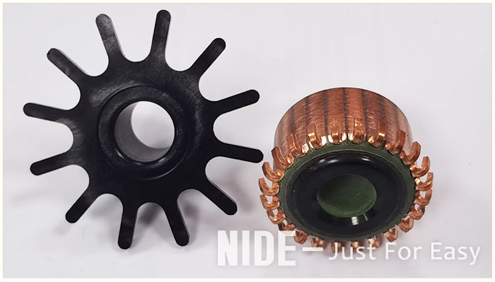
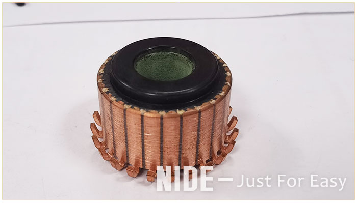
The commutator is widely used in the automotive field, household motors, and electric tools. The basic structure of the commutator is: including the commutator copper sheets evenly distributed on the outer circumference of the commutator body, and the commutator body. Formed together, the commutating copper sheet is provided with a piece of foot which is implanted into the commutator body and firmly combined with the commutator body.
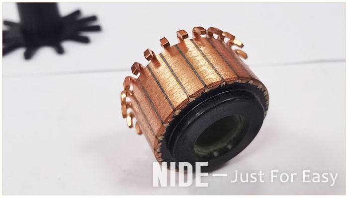
In order to strengthen the bonding strength between the commutator copper sheet and the commutator body, and improve the mechanical properties of the power tool commutator products, the most commonly used method is to improve the structure of the chip feet and set the reinforcement ring, and the improvement of the chip foot structure is the most ideal. The technical solution is to increase the size of the film feet. However, for power tool commutator products with small radial size and large number of commutation copper sheets, the size of its feet is strictly limited in both the circumferential and radial directions, and each adjacent commutation is strictly limited. The distance between the inner sides of the pins of the copper sheets will be very small. If the radial dimension of the pins is increased, the adjacent pins will easily touch when the commutating copper sheets and the commutator body are injected together. , resulting in a high rejection rate of commutator products after injection molding.
In order to strengthen the bonding strength between the commutator copper sheet and the commutator body, and improve the mechanical properties of the power tool commutator products, the most commonly used method is to improve the structure of the chip feet and set the reinforcement ring, and the improvement of the chip foot structure is the most ideal. The technical solution is to increase the size of the film feet. However, for power tool commutator products with small radial size and large number of commutation copper sheets, the size of its feet is strictly limited in both the circumferential and radial directions, and each adjacent commutation is strictly limited. The distance between the inner sides of the pins of the copper sheets will be very small. If the radial dimension of the pins is increased, the adjacent pins will easily touch when the commutating copper sheets and the commutator body are injected together. , resulting in a high rejection rate of commutator products after injection molding.
In view of the shortcomings of the existing technology, we provide a new commutator technical solution, which can improve the firmness of the combination between the commutator copper sheet and the commutator body, making a power tool commutator with higher product quality.
Send Inquiry

X
We use cookies to offer you a better browsing experience, analyze site traffic and personalize content. By using this site, you agree to our use of cookies.
Privacy Policy